Robot Dynamics & Control: Lecture 3 - Forward Kinematics: The Denavit-Hartenberg Convention
Introduction
The forward kinematics problem is to determine the position and orientation of the end-effector given the values of the joint variables of the robot. The joint variables are the angle between the links for a revolute (rotational) joint, and the link extension for a prismatic (sliding) joint.
$$ \begin{bmatrix} x \\ y \\ z \\ \psi \\ \theta \\ \phi \end{bmatrix} = f(\theta_1, \cdots, \theta_n, d_1, \cdots, d_n) $$where $f$ denotes the forward kinematics.
Kinematic Chains
A robot manipulator with $n$ joints will have $n+1$ links, including ground. Joints are numbered $1$ to $n$ and links $0$ to $n$. Joint $i$ connects link $i-1$ to link $i$, and joint $i$ is fixed to link $i-1$, so when joint $i$ is actuated, link $i$ moves. Link $0$, the first link, is fixed and does not move when the joints are actuated.
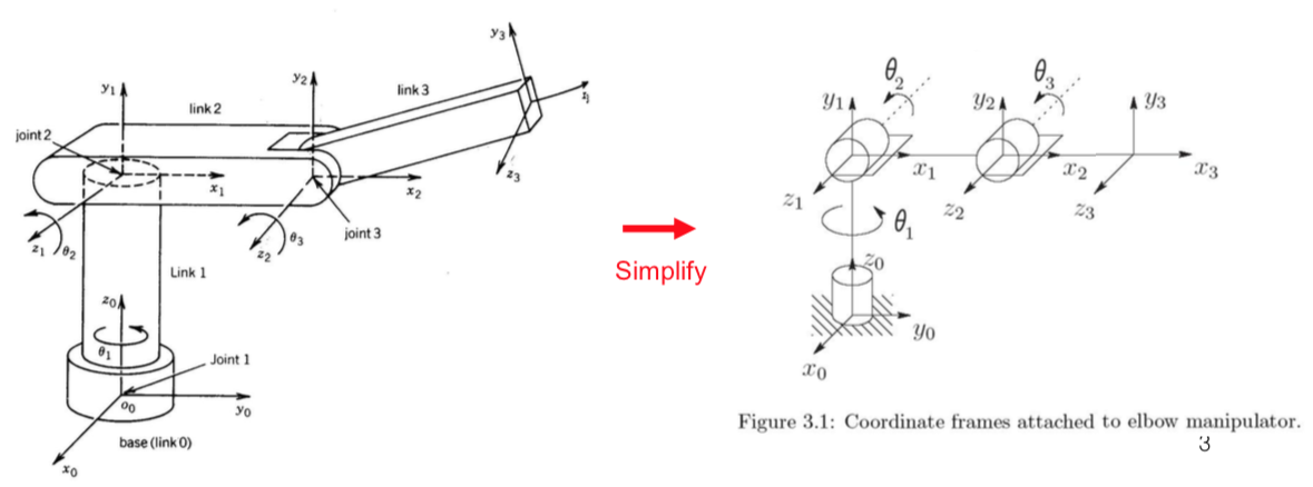
With the $i^{\text{th}}$ joint we associate a joint variable denoted by $q_i$:
- $\theta_i$ if joint $i$ is revolute,
- $d_i$ if joint $i$ is prismatic.
The frame $o_i x_i y_i z_i$ is attached to link $i$, so when joint $i$ is actuated, link $i$ and its attached frame $o_i x_i y_i z_i$ experience a resulting motion. The frame $o_0 x_0 y_0 z_0$, which is attached to the robot base, is referred to as the inertial frame (the world coordinate frame).
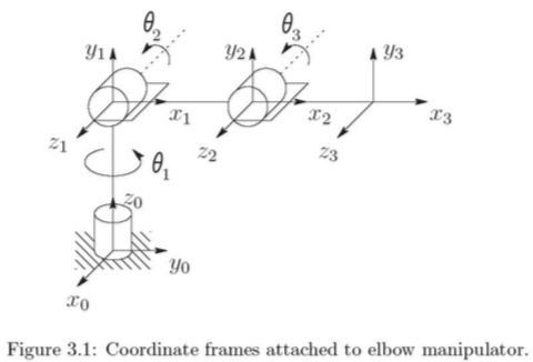
Suppose $A_i$ is the homogeneous transformation matrix that expresses the position and orientation of $o_i x_i y_i z_i$ with respect to $o_{i-1} x_{i-1} y_{i-1} z_{i-1}$. The matrix $A_i$ is not constant but varies as the configuration of the robot changes, and it is a function of only a single joint variable, namely $q_i$:
$$ A_i = A_i(q_i) $$Let $T^i_j$ be the homogeneous transformation matrix that expresses the position and orientation of $o_j x_j y_j z_j$ with respect to $o_i x_i y_i z_i$:
$$ \begin{aligned} T^i_j &= A_{i+1} A_{i+2} \cdots A_{j-1} A_j & &\text{if } i < j \\ T^i_j &= I & &\text{if } i = j \\ T^i_j &= \left(T^j_i\right)^{-1} & &\text{if } i > j \end{aligned} $$The homogeneous transformation matrix that expresses the position ($o^0_n$) and orientation ($R^0_n$) of the end-effector with respect to the inertial or base frame is
$$ \begin{aligned} H &= \begin{bmatrix} R^0_n & o^0_n \\ 0 & 1 \end{bmatrix} \\ &= T^0_n \\ &= A_1(q_1) \cdots A_n(q_n) \end{aligned} $$This is the forward kinematics. A considerable amount of streamlining and simplification is possible by introducing the D-H representation.
Each homogeneous transformation matrix has the form
$$ A_i = \begin{bmatrix} R^{i-1}_i & o^{i-1}_i \\ 0 & 1 \end{bmatrix} $$and hence
$$ T^i_j = A_{i+1} \cdots A_j = \begin{bmatrix} R^i_j & o^i_j \\ 0 & 1 \end{bmatrix} $$ $$ \begin{aligned} R^i_j &= R^i_{i+1} \cdots R^{j-1}_j \\ o^i_j &= o^i_{j-1} + R^i_{j-1} o^{j-1}_j \end{aligned} $$It is possible to carry out all of this analysis using an arbitrary frame attached to each link. However, it is helpful to be systematic in the choice of these frames by using the Denavit-Hartenberg (D-H) convention, in which each homogeneous transformation matrix $A_i$ is represented as a product of four basic transformations.
Denavit - Hartenberg Representation
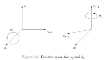
$$ \begin{aligned} A_i &= Rot_{z,\theta_i}\, Trans_{z,d_i}\, Trans_{x,a_i}\, Rot_{x,\alpha_i} \\ &= \begin{bmatrix} c_{\theta_i} & -s_{\theta_i} & 0 & 0 \\ s_{\theta_i} & c_{\theta_i} & 0 & 0 \\ 0 & 0 & 1 & 0 \\ 0 & 0 & 0 & 1 \end{bmatrix} \begin{bmatrix} 1 & 0 & 0 & 0 \\ 0 & 1 & 0 & 0 \\ 0 & 0 & 1 & d_i \\ 0 & 0 & 0 & 1 \end{bmatrix} \begin{bmatrix} 1 & 0 & 0 & a_i \\ 0 & 1 & 0 & 0 \\ 0 & 0 & 1 & 0 \\ 0 & 0 & 0 & 1 \end{bmatrix} \begin{bmatrix} 1 & 0 & 0 & 0 \\ 0 & c_{\alpha_i} & -s_{\alpha_i} & 0 \\ 0 & s_{\alpha_i} & c_{\alpha_i} & 0 \\ 0 & 0 & 0 & 1 \end{bmatrix} \\ &= \begin{bmatrix} c_{\theta_i} & -s_{\theta_i}c_{\alpha_i} & s_{\theta_i}s_{\alpha_i} & a_i c_{\theta_i} \\ s_{\theta_i} & c_{\theta_i}c_{\alpha_i} & -c_{\theta_i}s_{\alpha_i} & a_i s_{\theta_i} \\ 0 & s_{\alpha_i} & c_{\alpha_i} & d_i \\ 0 & 0 & 0 & 1 \end{bmatrix} \end{aligned} $$Since the matrix $A_i$ is a function of a single variable, three of the four quantities are constant for a given link:
- $d_i$ is the joint variable for a prismatic joint,
- $\theta_i$ is the joint variable for a revolute joint.
By a clever choice of the origin and coordinate axes it is possible to cut the number of parameters needed from six to four.
Existence and uniqueness
Clearly it is not possible to represent an arbitrary homogeneous transformation using only four parameters. But it is possible to derive a unique homogeneous transformation matrix $A$ under the following two conditions:
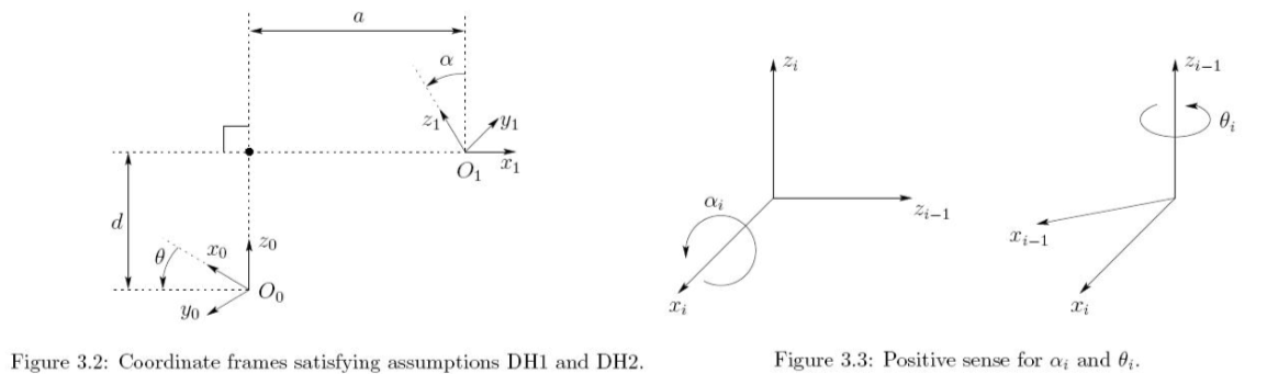
DH1) The axis $x_1$ is perpendicular to the axis $z_0$.
DH2) The axis $x_1$ intersects the axis $z_0$.
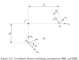
Under DH1 and DH2 we claim that there exist unique numbers $a$, $d$, $\theta$, $\alpha$ such that
$$ A = Rot_{z,\theta}\, Trans_{z,d}\, Trans_{x,a}\, Rot_{x,\alpha} $$The physical interpretation of the four quantities is:
- $a$: distance between the axes $z_0$ and $z_1$, measured along the axis $x_1$.
- $d$: distance between the origin $o_0$ and the intersection of the $x_1$ axis with $z_0$, measured along the $z_0$ axis.
- $\alpha$: angle between the axes $z_0$ and $z_1$, measured in a plane normal to $x_1$.
- $\theta$: angle between $x_0$ and $x_1$, measured in a plane normal to $z_0$.
Assigning the coordinate frames
For a given robot manipulator one can always choose the frames $0, 1, \ldots, n$ in such a way that DH1 and DH2 are satisfied. It is important to keep in mind that the choices of the various coordinate frames are not unique, even when constrained by DH1 and DH2. It is equally important to note that the end result $T^0_n$ will be the same regardless of the assignment of the intermediate link frames.
We assign $z_i$ to be the axis of actuation for joint $i+1$: if joint $i+1$ is revolute, $z_i$ is its axis of revolution; if joint $i+1$ is prismatic, $z_i$ is its axis of translation.
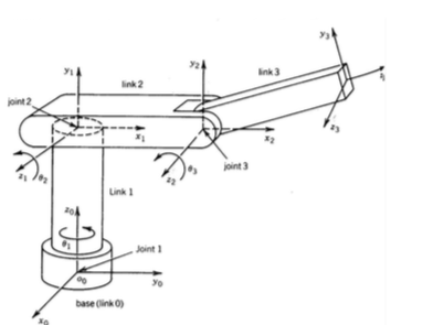
In order to set up frame $i$ it is necessary to consider three cases.
Case 1. $z_{i-1}$ and $z_i$ are not coplanar.
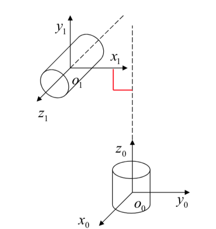
Case 2. $z_{i-1}$ is parallel to $z_i$; here $d_i$ and $\alpha_i$ are zero.
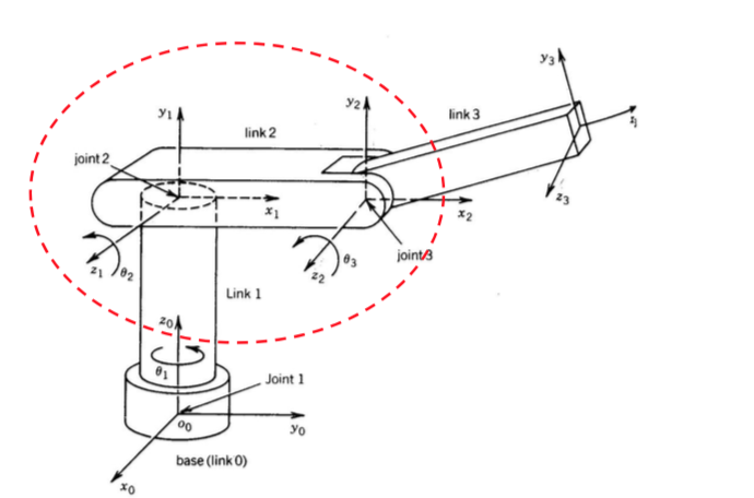
Case 3. $z_{i-1}$ intersects $z_i$; here $a_i$ is zero.
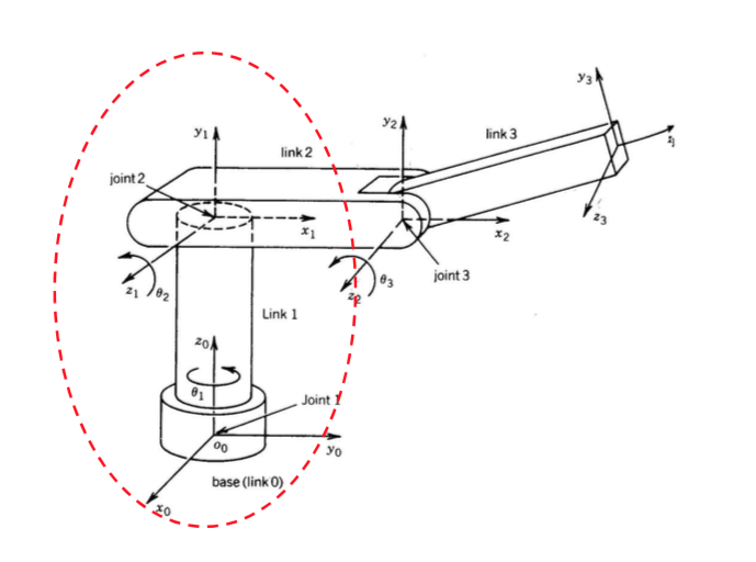
This constructive procedure works for frames $0, \ldots, n-1$ in an $n$-link robot. The final coordinate system $o_n x_n y_n z_n$ is commonly referred to as the end-effector (or tool) frame.
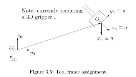
The terminology arises from the fact that the direction a is the approach direction, the s direction is the sliding direction, and n is the direction normal to the plane formed by a and s.
Note the following important fact. The quantities $a_i$ and $\alpha_i$ are always constant (they are characteristics of the manipulator). If joint $i$ is prismatic, then $\theta_i$ is also a constant while $d_i$ is the $i^{\text{th}}$ joint variable; if joint $i$ is revolute, then $d_i$ is a constant while $\theta_i$ is the $i^{\text{th}}$ joint variable.
Summary
Step 1. Locate and label the joint axes $z_0, \ldots, z_{n-1}$.
Step 2. Establish the base frame. Set the origin anywhere on the $z_0$-axis. The $x_0$ and $y_0$ axes are chosen conveniently to form a right-hand frame. For $i = 1, \ldots, n-1$, perform steps 3 to 5.
Step 3. If $z_i$ intersects $z_{i-1}$, locate $o_i$ at this intersection. If $z_i$ and $z_{i-1}$ are parallel, locate $o_i$ in any convenient position along $z_i$.
Step 4. Establish $x_i$ along the common normal between $z_{i-1}$ and $z_i$ through $o_i$, or in the direction normal to the $z_{i-1} - z_i$ plane if $z_{i-1}$ and $z_i$ intersect.
Step 5. Establish $y_i$ to complete a right-hand frame.
Step 6. Establish the end-effector frame $o_n x_n y_n z_n$. Assuming the $n$-th joint is revolute, set $z_n = $ a along the direction $z_{n-1}$. Establish the origin conveniently along $z_n$, preferably at the center of the gripper or at the tip of any tool. Set $y_n = $ s in the direction of the gripper closure.
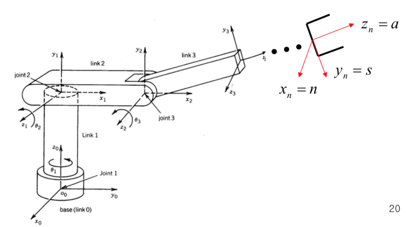
Step 7. Create a table of link parameters $a_i, \alpha_i, d_i, \theta_i$.
Step 8. Form the homogeneous transformation matrices $A_i$ by substituting the above parameters into
$$ \begin{aligned} A_i &= Rot_{z,\theta_i}\, Trans_{z,d_i}\, Trans_{x,a_i}\, Rot_{x,\alpha_i} \\ &= \begin{bmatrix} c_{\theta_i} & -s_{\theta_i}c_{\alpha_i} & s_{\theta_i}s_{\alpha_i} & a_i c_{\theta_i} \\ s_{\theta_i} & c_{\theta_i}c_{\alpha_i} & -c_{\theta_i}s_{\alpha_i} & a_i s_{\theta_i} \\ 0 & s_{\alpha_i} & c_{\alpha_i} & d_i \\ 0 & 0 & 0 & 1 \end{bmatrix} \end{aligned} $$Step 9. Form $T^0_n = A_1 \cdots A_n$. This gives the position and orientation of the tool frame expressed in base coordinates.